


PRODUCTS
- Device for RoF Application
- Isotropic optical E-field sensor head/Optical probe head
- OPTICAL PROBE for malfunction noise


OEFS:Optical E-Field Sensor
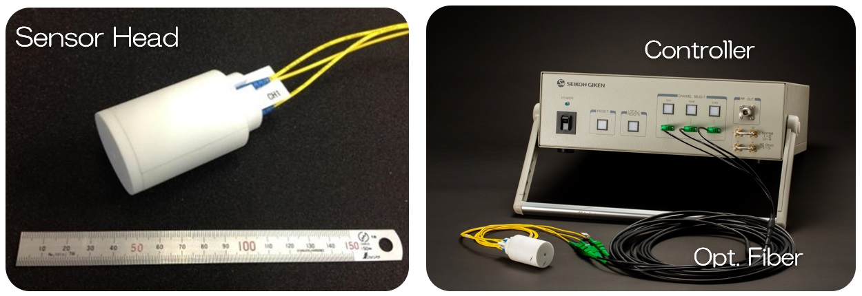
Our OEFS enables accurate E-field intensity measurement with a small sensor head utilizing the electro-optic effect.
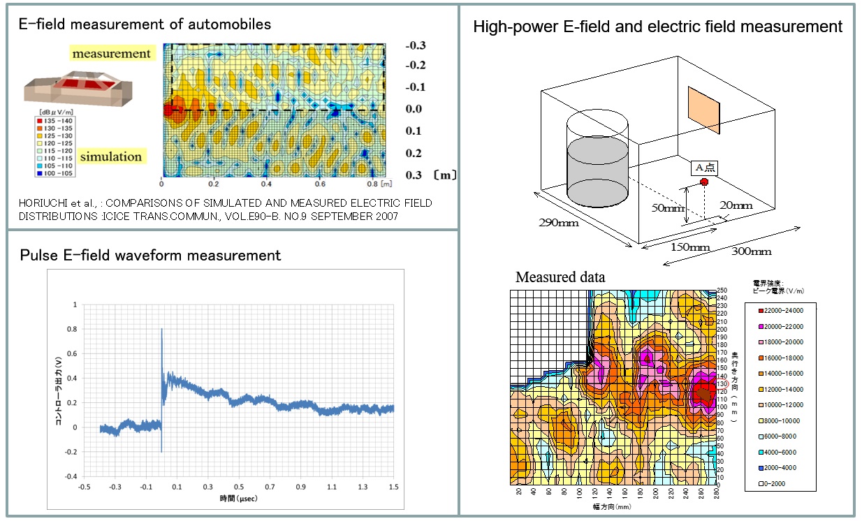
It is used for various purposes such as verification of simulation model in EMC design, pulse E-field waveform measurement, measurement of high-power E-field and electric field measurement in a narrow space.
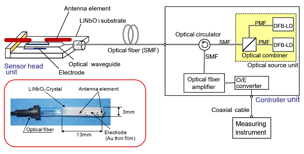
System Diagram of OEFS
Optical electric field sensor head : Standard products
| Model number | SH-10TS | SH-10SL | SH-10SS |
|---|---|---|---|
| Frequency | ~10GHz | ||
| E-field strength range | 0.01~500V/m | 0.5~25,000V/m | |
| Isotropy | ±1dB typ. | - | |
| Sensor head size | Φ40X90mm | 10X10X55mm | |
| Features | Isotropic Triaxial | Single axis | |

 SH-10TS(378KB)
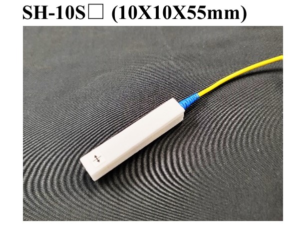
Optical Probe
Our optical probes convert voltage signals to optical signals with a small probe head utilizing the electro-optic effect.
It is used for various purposes such as evaluation of small antennas.
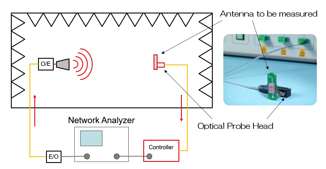
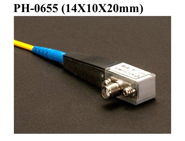
Optical probe head : Standard products
| Model number | PH-0655 |
|---|---|
| Frequency | 100M~6GHz |
| Transmission loss | -25dB typ. |
| Probe head size | 14X10X50mm |
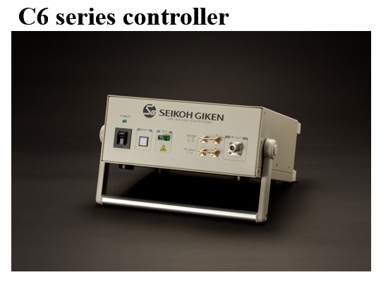
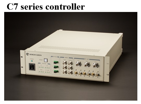
Controller
Controllers for OEFS can be selected from the following three types.
| Model number | Features |
|---|---|
| C5 series controller | 3-axis switching type |
| C6 series controller | Single axis type |
| C7 series controller | 3-axis simultaneous output type |
| Adobe Reader is required to open the pdf files above. Click here to download a free copy. |
Inquiry by telephone:+81-47-388-6197
(Electric field products - Sales manager)
Mon~Fri 8:30~17:30
![]()
PAGE TOP